How-To: Install your Hugh’s HandBuilt PMA System on your XS650
Seeing as how we developed the first Complete Permanent Magnet Alternator Conversion for your XS650, we should supply our customers with only the finest install instructions. So we are proudly giving you all new and updated install information here!
So here we go! All new PMA Install instructions, specific to HHB PMA goodness!
First things first, lay out your Genuine Hugh’s HandBuilt PMA System. Identify each component, and make sure it is complete before starting. For this How-To Install Thread, we will be installing one of our PMA systems on an engine that is out of the chassis.

The beauty of the PMA system is that you can even get an XS650 engine running without installing it in a bike, and charging too! I could show you how to remove the left side peg and mounts, remove the pipes (if needed) and disconnect the clutch cable, remove the side cover, expose the OEM charging system, unplug the OEM charging system from the OEM wiring harness (if you still have one, most people can justify rewiring a 28-42 year old bike anyhow) unbolt the factory Regulator and Rectifier, and open up your favorite beverage to do so, but if I had to describe every single part of that, you might just be in over your head wrenching on your XS650.
So don’t fret, this is much easier than you think! Just remove everything I mention above, and you are ready to go (OEM pipes may not need to be removed, some aftermarket pipes may be, use your own judgement)
You should have all of the components seen here:

Now go gather some tools.

You’ll want the following:
Small Hammer
Small Punch (brass preferably, but any will do so long as you are gentle with your work)
#3 Phillips Screw Driver
5mm Allen Wrench
4mm Allen Wrench
5mm Allen Driver (not required, but nice to have – the one shown is much longer than needed)
Torque Wrench (Not shown in the above picture)
3/8 Ratchet
17mm Socket
Wire Strippers/Crimpers
OEM Rotor Puller (or a 2 jaw puller if you don’t plan to resell the OEM Rotor)
Small pair of Vice Grips
Now, onto removing that old charging system. But we got a few small things to do first.
Remove the alternator cover from the side cover. If you haven’t done this in a while, and the hardware is cruddy, it’s MUCH easier to do with the main cover still attached to the engine. (*Note – the chrome clutch adjustment cover is also removed, not required for this swap, just so happened to be off for this shot)

Now pull the rest of the side cover off

You won’t be so lucky to have the wiring already tidied up like above. You’ll have to remove the chain guard from the engine, it slips over the shift shaft. I usually leave them off of my builds, so you won’t see it here. That will require a 10mm socket and a 12-13mm wrench depending on the year of your engine.
Disconnect all the wiring from the charging system to the bike itself. You will have a blue wire that goes to the neutral switch on the cases. Disconnect it as well (you can rewire it later if you want)
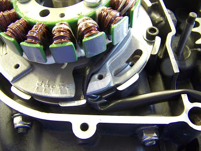
You are now looking at something similar to this. This is from a TCI (80-84) bike, so you will notice a few differences if your bike was originally equipped with points ignition. On a TCI engine you WILL have to change out to a Pamcopete, Points, Boyer, etc.. ignition. That’s a good thing – and I prefer Pamcopete myself for a very simple and cost effective igntion system on an XS650.

Now, to simplify a few things down the road, rotate the engine to TDC. That’s the “T” mark on your timing tab. Use the ratchet and a 17mm socket to do this part.

You should be looking at something like this (*Note – if you have a different looking tab on your charging system, that’s ok, just set it to “T” just like mentioned above. That’s all that matters)

Remove the old alternator housing using a #3 Screwdriver, or a 5mm Allen Wrench (depending on the hardware already installed – feel free to use the vice grips if these don’t wanna come out easy, you won’t be keeping them)
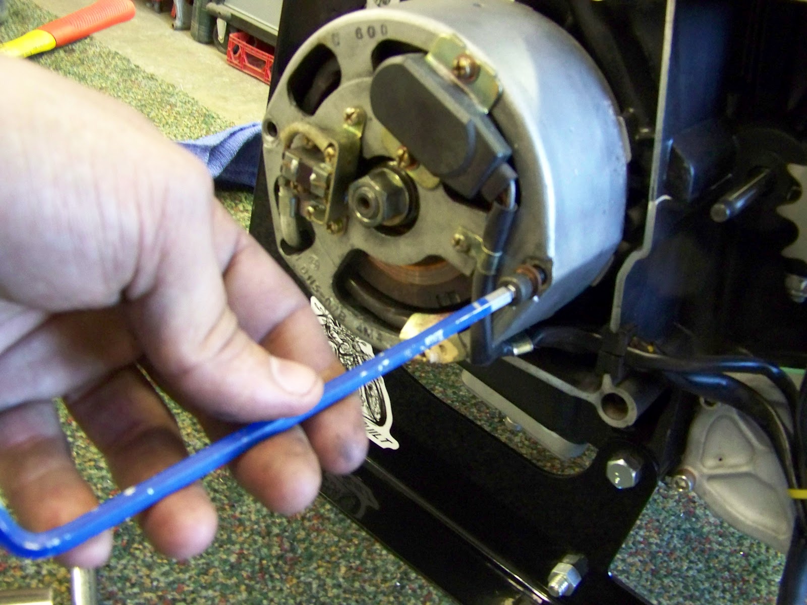


Again, I use the Impact gun to get the rotor off – but you can use 2 wrenches as well.

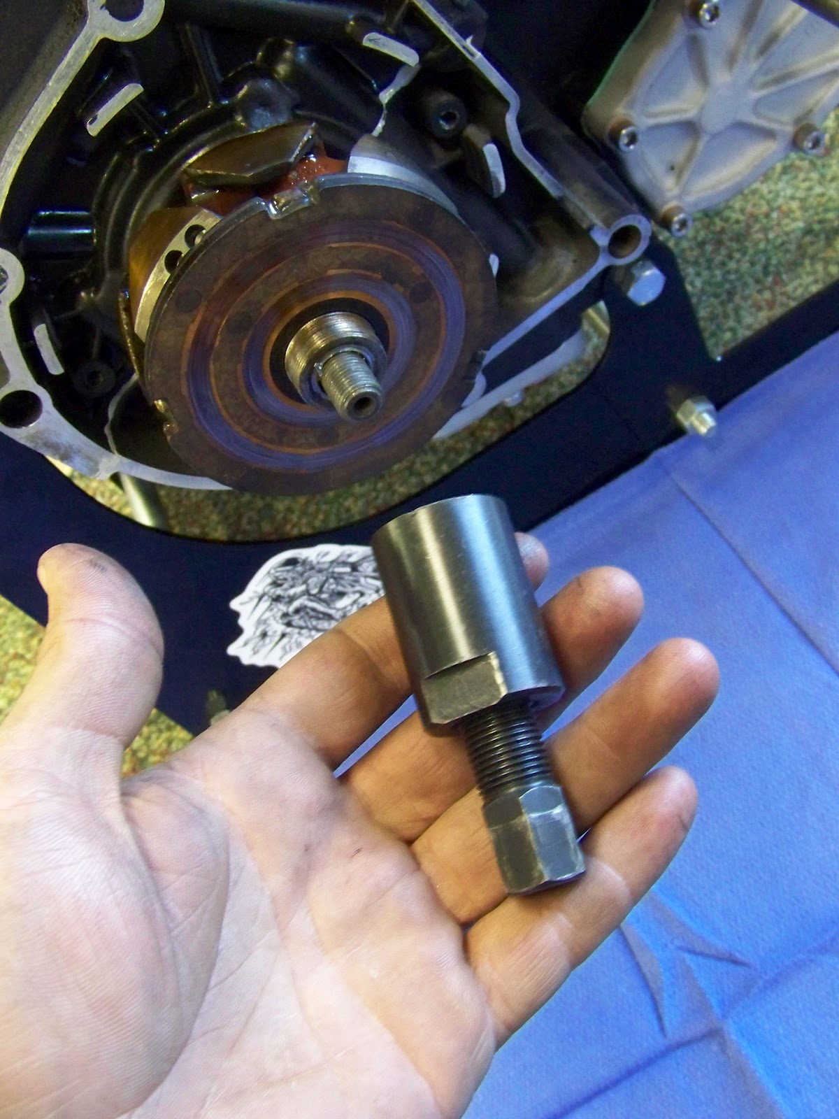
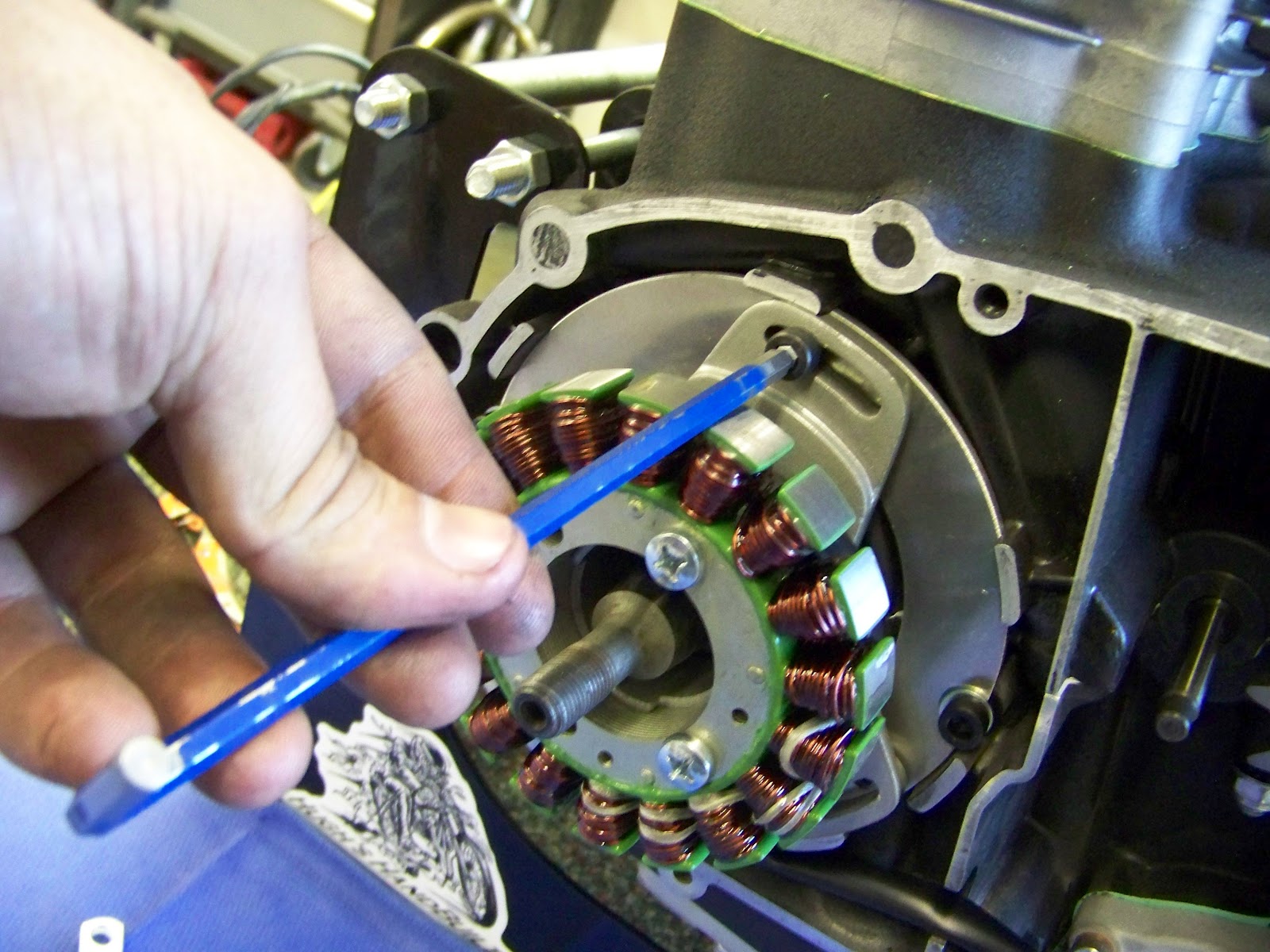
You are now looking at the exposed crank end, it’s all naked and bashful, it hasn’t seen daylight in a while, so be nice to it. Be careful not to knick, pry, or damage the crank. If you have a bunch of oil back behind the OEM charging system, now is a good time to replace the crank seal as well.

Now, if your crank moved at all during removal of these parts, don’t sweat it. You can do a “light” reinstall of the OEM components, no need to install the hardware, and using your hands you can turn the crank using the OEM rotor, and see if the timing marks line up with the alternator housing. Once you have them lined up again, pull it all off. This is a simple way to keep your timing marks proper, as compared to using a dial indicator, finding TDC using a special stop in the spark plug hole, etc… As with anything, if you have the tools to find TDC in a better manner, go for it, but this way works for 99% of the folks doing this seap.
Now that you are happy with the engine being at TDC, lets get rid of a few things.
See this woodruff key? It’s no longer needed, pull that sucker out! Sometimes it will come right out, other times you will need some pliers/vicegrips to grab it. I had to use Vice Grips today.

Get that sucker out of there! (Previous install threads mentioned making a whole new woodruff key, but you won’t need to do so. All the woodruff key does is locate the OEM rotor on the crank for timing mark reference. We’ll be making new timing marks, and the taper on the crank matches the new flywheel perfectly for a precision fit.)


Now, lets get to installing the NEW Charging System.


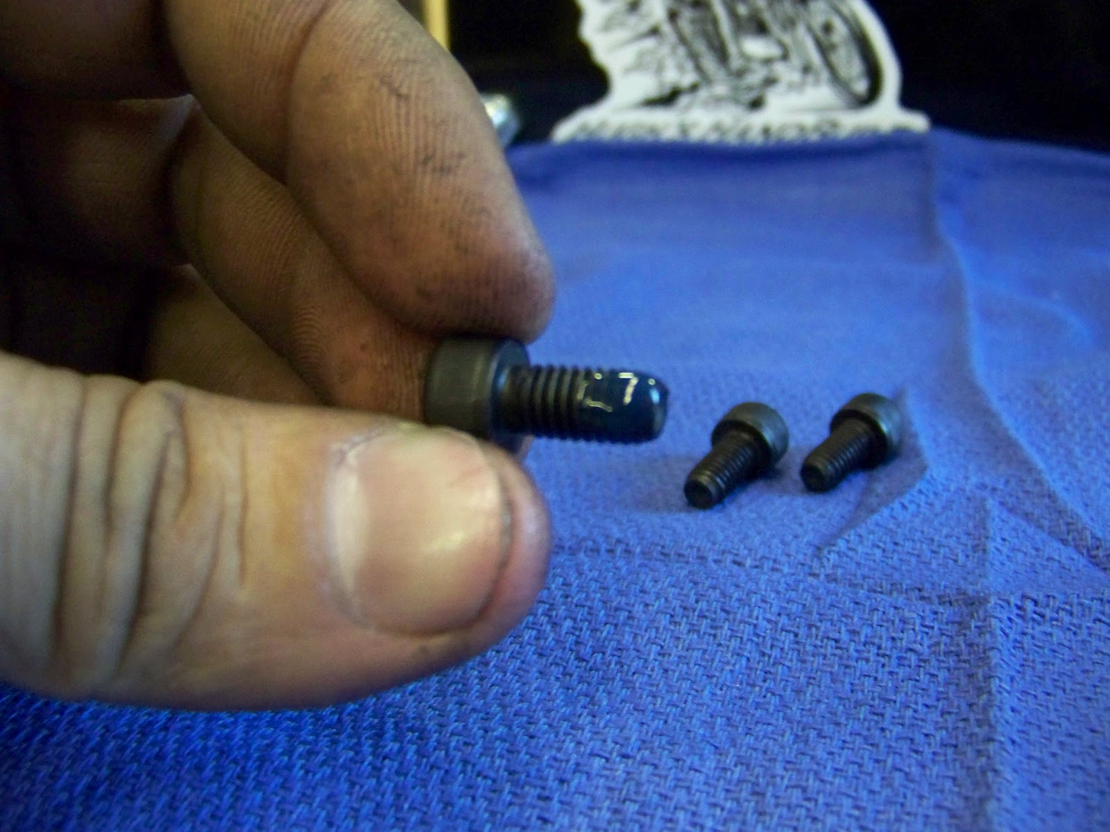
Get the 2 longer socket bolts and the 2 washers, these will fasten the bracket to the engine cases. You’ll use the 5mm allen wrench.

Use Blue Locktite on ALL hardware on the PMA swap.

Use sparingly, and yes, you have to put it ON the threads. I wish I didn’t have to say that, but I had a “friend” put it in the head of the hardware thinking it would somehow work its way into the threads – or some kinda crap.. All I know, is that those “Warning” and “Caution” signs that we all think are obvious (like the one with the people taking a bath while using a toaster) are there because someone apparently didn’t know any better. Ok, Rant Off

Install the hardware in the cases. You will want to torque these to 7 Ft Lbs. Do not overtighten them, or use them to pull the plate flat against the cases.

Now grab the stator mount, and stator.

Line up the holes in the stator with the holes in the stator mount. Make sure all 3 holes in the stator line up with the threaded holes in the stator mount. The wires on the stator should be coming out of the back of the stator, like below.

Get the 3 Phillips Headed screws from the hardware kit, and a little more blue locktite.

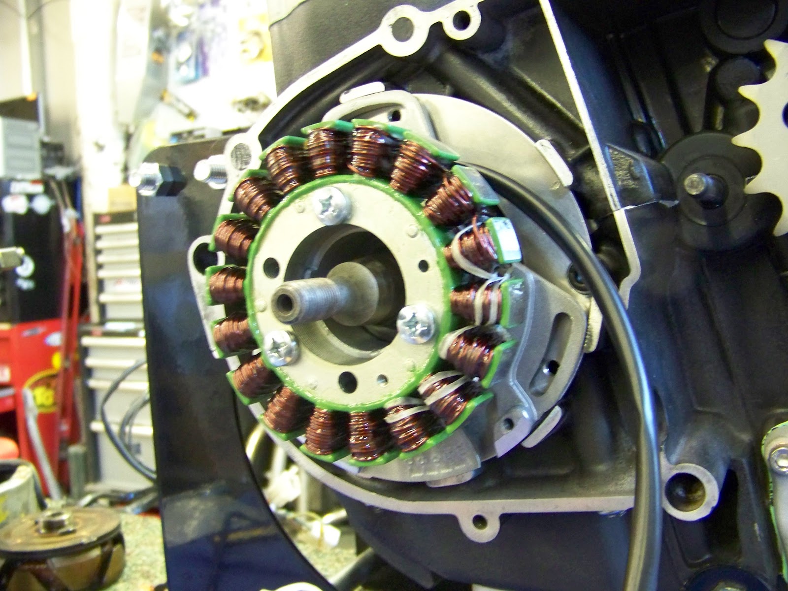
Install the 3 screws using a #3 screwdriver. You can snug these up to a good grunt. Repeat the tightening of each screw a few times until the stator is fully seated against the mount.

Starting to look pretty good at this point. You are well on your way if your work looks alot like this.

Get the protective sleeving that comes with the stator, and slip it over the 3 yellow wires.

Slip it all the way up, and then around the stator as far as it will go.


You’ll notice I already positions the stator mount up against the PMA Adapter at this point. Don’t install the hardware just yet.
Wrap the sleeved and protected wiring clockwise around the backside of the stator, as pictured below. Make 100% sure that the wiring is snugly wound against the stator mount. You want to ensure that the wiring cannot become loose and come into contact with the moving rotor at anytime.
On your stator mount, you can bring the wiring just under the bracket, and then clock the stator mount against the PMA Adapter to hold the wiring out of the way. Just like you see below… Make 100% sure that your wiring is well out of the way of the flywheel when the engine will be running. Snug and secure wiring is the ticket here..

Once you have the wiring routed around the stator and stator mount, you can finish mounting the stator mount to the PMA Adapter Plate. Use the 3 supplied socket head screws. Do not use washers here.

I bet you already guessed it, but yes, you will be using some more blue locktite here.
Double, then triple check that the stator mount is seated fully against the PMA Adapter plate. This isn’t as critical if your engine is clean. Use the same method as you did previously with the soft punch and hammer.

Now, you can install the hardware using your 5mm allen wrench. Do NOT overtorque this hardware. It gets torqued to 3 Ft Lbs.
Now that the Stator is completely mounted, you will want to make sure all the hardware is torqued properly. All the hardware supplied should be torqued to proper specs. Be careful not to overtighten these. “Hand Tight and then a tad” is perfect

Finish routing the wiring on the engine. I supply a vinyl protected loop for just the job. I remove the upper middle bolt from the starter gear box cover, position the wiring out of the way, and then install the loop onto the engine. Routing your wiring under the shift shaft will keep it out of the way of the chain/gear and make your install that much cleaner.

Wiring on the engine is all buttoned up at this point.

Now lets install the PMA Flywheel.


Then use the original lockwasher and nut that was removed earlier, and torque the flywheel to spec. 25-29 Ft Lbs should do it. Get a friend to help keep the engine from rotating while doing so. If needed, make a small reference mark between the rotor and the cases while doing this, and then you can go back to where you were after tightening the nut. We still want to keep the engine at TDC until we make new timing marks on the flywheel.

You are seriously near the finish line now. Onto the side covers and the timing marks.
Apply the HHB timing Sticker to your side cover. Make sure to clean the mounting surface with brake cleaner/acetone/etc.. so that the sticker has a good clean surface to adhere to.

If you are clumsy fingered like I am with stickers, then it will look alot like this. If not, then you’ve done a really good job!

Mount the side cover back up on our engine.

I like to use a bright paint pen for my timing marks, but you can use anything so long as it is gonna let you know where TDC is. Make a nice visible mark to match up to the “TDC” mark on the sticker.

*It should be mentioned, that making new timing marks does NOT require you to retime your engine. I have plenty of customers who’ve never made a single timing mark on their PMA system. I just offer this bit of tech to help those who want to do so. If you already have Points/Pamco/Boyer or any other cam triggered ignition installed, and running before the PMA swap, then you can just bolt on and go. if you are installing a new ignition at the same time – then you will want to re-time your engine, and this makes it MUCH easier than playing a guessing game.
Button up the side cover. It’s like nothing ever happened!

Now onto the last bit, the regulator wiring.
Get your regulator, and identify the 3 yellow wires coming from it. *Note – DO NOT CUT or REMOVE the Regulator/Rectifier plug containing the 3 yellow wires or the warranty is void on the Regulator/Rectifier.


These 3 yellow wires are going to hook up the the 3 yellow wires that come from the PMA Stator. In no particular order, just make sure each wire from the stator gets it’s own connection to the regulator/rectifier.
*At this point, you will want to figure out where you want to locate your PMA Regulator/Rectifier on your bike. There is plenty of wiring on the stator, but for a tidy install, you may need to trim down the wiring from the stator a bit. The PMA Regulator will mount in the stock location of most XS650’s, or if you are building a custom bike, you’ll need to locate it somewhere in the open. Do NOT mount it in an enclosed box, it needs airflow to operate properly.
A QUICK NOT ABOUT WIRING! READ THIS LINK, Or take a chance on voiding your warranty!
Get the 3 male terminals from the wiring kit supplied with the PMA Stator. Strip back a small amount of insulation from the 3 yellow wires coming from your stator.

Crimp the terminals onto the wiring. There is a small crimp for the copper wiring, and another for the insulation. Make sure to crimp both well and then *SOLDER the connections properly. YOU MUST SOLDER ALL PMA Connections. (See below for warranty and install details)

Now get the female connector housing that is supplied with the PMA kit. It looks like this:

You will notice that the electrical terminals have a “tab” on them. Push the terminals into the plastic housing with the “tab” facing outwards. You will feel/hear them click into place.

Finish the other 2 connectors/terminals.

If your regulator was installed on your bike (unlike in my how-to) then you would just connect the stator to the regulator/rectifier at this point. A simple plug and play setup

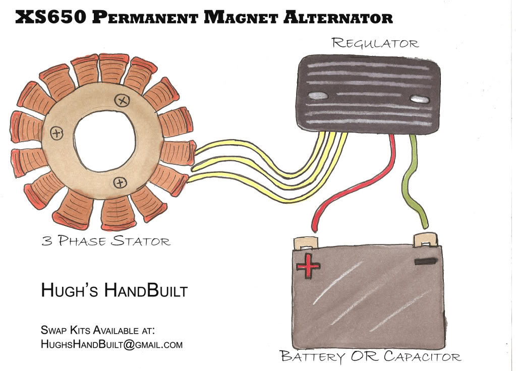
Ok, so now you have the stator supplying power to the regulator/rectifier – congrats! But what about those other 2 wires coming from the Regulator/Rectifier? It doesn’t get any easier than this – red goes to the postive (+) terminal on your battery (or capacitor) and the green wire is your ground. You can ground directly to the battery (or capacitor) or directly to the chassis. Just make sure you connect a ground from the chassis to the battery (or capacitor) if you go that route, and you are DONE with your PMA swap!

Here is a simple wiring diagram in case you have trouble seeing the whole picture..
Well folks, I have written this PMA Tech Article in the past, but a few things have changed now that we market and sell a Complete PMA System for your XS650. I’ve had a really good thread on the Chopcult and on XS650.com in the past, but unfortunately other vendors started selling PMA’s and pointing their customers to HHB for tech and install help using our How-To’s and Tech for their install instructions. I didn’t mind it at first, because I genuinely want everyone with an XS650 to enjoy their bike/build to the fullest.
I wish I could afford the 7-10 hours a week I was spending helping my competition’s sales and offering free tech, but I just can’t do it any longer. I want to focus on more product design, and offering more parts/services to the XS650 Enthusiasts around the world who are enjoying their machines. If you have been pointed to this after purchasing your PMA from a competitor, give yourself some time to think why they would point you here? We have spent a great deal of time and money to make only the finest components and services available to XS650 enthusiasts, because we really know these machines inside and out.
As always, if you have purchased a Genuine HHB product, and need help/advice/wanna just shoot the bull, shoot us an email at HughsHandBuilt@gmail.com and we’ll take care you you. Customer service is a major priority for HHB, and you deserve that from a business who you have spent your hard earned money with.
Enjoy building your bikes, and stay creative. But most of all, have fun with this! And thanks for your continued support of Hugh’s HandBuilt
Hugh Owings
*Warranty Information for Install: You MUST solder the connections from the stator to the supplied male terminals before sliding the male terminals into the white plastic connector block. Do NOT cut off or remove the 3 yellow terminals from the Regulator/Rectifier – they must be kept in place. This is to help ensure that your system operates properly and that your wiring is tidy and reliable. Thanks so much.


Do u have an image of how the new regulators are connected?
Ryan
I don’t – but its pretty straight forward stuff. 3 Yellows Connect to the same from the Stator. The remaining wires connect to the battery/Capacitor as needed.
Hugh
Thank you High for this amazing description and unselfish demonstration to share your knowledge with others . Thank you . May you grow better and your hands and brain function more to contribute to the xs world !!
Thanks for offering individual components for the swap!
Hugh I have a pma on my 650 chopper for 3 years now and it’s still running strong,,well now it’s time to put o e on my newly acquired 75 stock rider ,,I am a believer in your pma and anyone that owns a 650 ,,this is a solid investment,,thank you so much
I like the drawing of the alternator / regulator / battery. Since I’ve upgraded to the PMA, I’ve roasted up two safety relays. My supply to the safety relay comes from one of the yellow wires off of the alternator, but I’m wondering if I should have spliced into the red wire coming out of the regulator to be my supply to the relay. Is it possible that the “raw” output from the alternator is supplying too much current to my relay and fusing it in the energized position? If you were to include the safety relay in the alternator / regulator / battery drawing, where would you put it?
**HHB Response: We do not recommend any hookup to the yellow stator wires other than the Regulator of course. Those Safety Relays were designed to turn the lights off when using the electric starter, but modern battery technology is so good now, I don’t even use the Safety Relay on any of my builds.